I have a VCU which looks for CAN messages to enable PRND. Is there a way to program buttons of the CAN keypad to transmit a CAN message for each P, R, N, D? The buttons should be in their own Radio Button Group as well.
I have the messages which the VCU expects for each P, R, N or D.
How complex is the CAN message? You can use a CAN export to send a custom message, might need to be a number function between the keypad button and CAN message, but using a custom multiplier on the CAN message might do.
Alternatively you can setup a table with each button state correlating to a value and transmit the table value.
This software is so flexible there’s a few ways to tackle it
I’m not sure how to set any of those options up. Can you point me in the right direction to a website or video on how to do that? I haven’t been able to find anything on setting up tables with button states. The software is so flexible yet the user manual is so vague, it assumes you already know how to do all of these things.
Then we’ll make a table that essentially just converts the button state into the numbers the CAN message needs to see.
In the data you posted the first Byte is the only one changing. We take the hexadecimal value and convert to decimal to get the following
0x0D = 13 (drive)
0x0E = 14 (neutral)
0x0F = 15 (reverse)
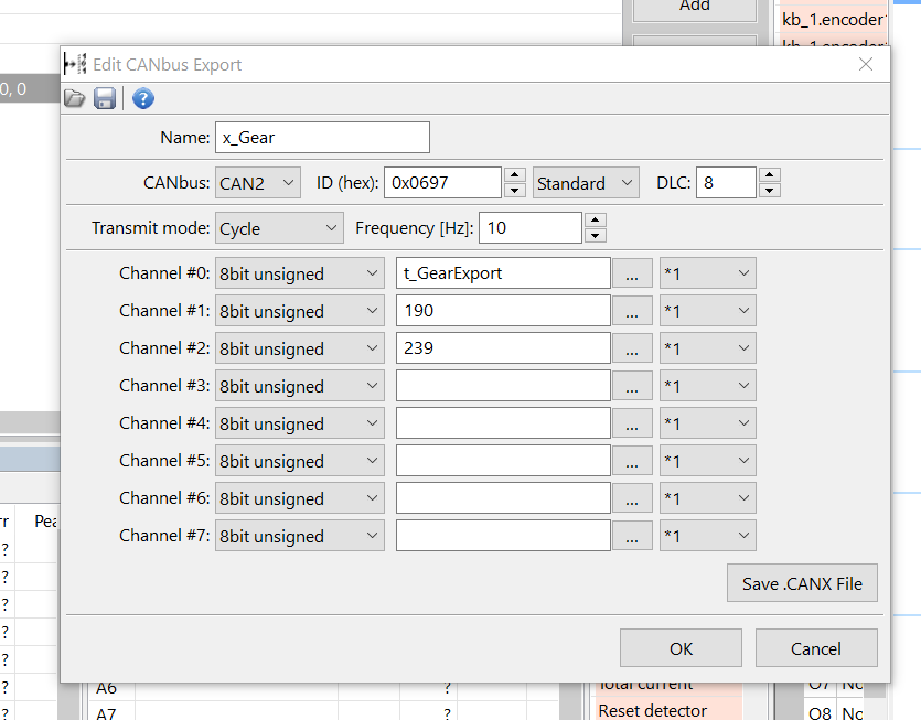
We then make a CAN export (outgoing message) on the given addess (0x697, Unsure if your data the address is supplied in decimal or hexadecimal. Ecumaster it’s asked for in hex, if the trans wants decimal then change to x2B9)
First Byte will be the table value that changes depending on requested gear, the rest are from the supplied data. When transmitted they are always in hex, so we give the software decimal.
0xBE = 190
0xEF = 239
0x00 = 0 (leave blank is fine)
Make sure the CAN bus is set to the one the trans is on (bus 1 or 2), and that should work.
I hear you on the manual, it’s a natural consequence that the more flexible a software is the harder it is to explain. Trial and error has been the way I’ve taught myself most things in it.