I can only upload it like this, it wont allow me to poste it here
But i have been going trough the help windows and I see that for wasted spark, the ecu is still wired up with all 4 ign outputs, even in wasted spark.
I can only upload it like this, it wont allow me to poste it here
But i have been going trough the help windows and I see that for wasted spark, the ecu is still wired up with all 4 ign outputs, even in wasted spark.
Also change those outputs to match your Ignition Outputs Parameters
I have mached the parameters and checked the box. But i think the ECU does not recognise that the engine needs ignition events.
I think of this in 2 reasons.
First one: When cranking and using a test light, it will only fire once so often and not like it should. but when i check the logs it wil state like 16 igniton events, but the light went off maybe 2x

Second, sometimes when cranking there are no ignition events at all.
I will attach a video of the light while cranking and a SCOPE of the main crank sensor, which is new and i think it is registered nicely
No Cam Shaft signal?
there is no cam sensor stock, only crank sensor.
Can you show us the wires that come from the coilpack in which pins you have set them in the ecumaster plugs ?
Are you sure you have +12v during cranking or before cranking on your middle pin plug at the coilpack ?
Why 43 Trigger tooths ? If your ignition stroke is on the other bank just switch the outputs on your wiriing plug (use a small razor to lift the tab and pull)
Coil dwell for this coilpack is minimum what you have, choose 6A or 7A settings for a good measure.
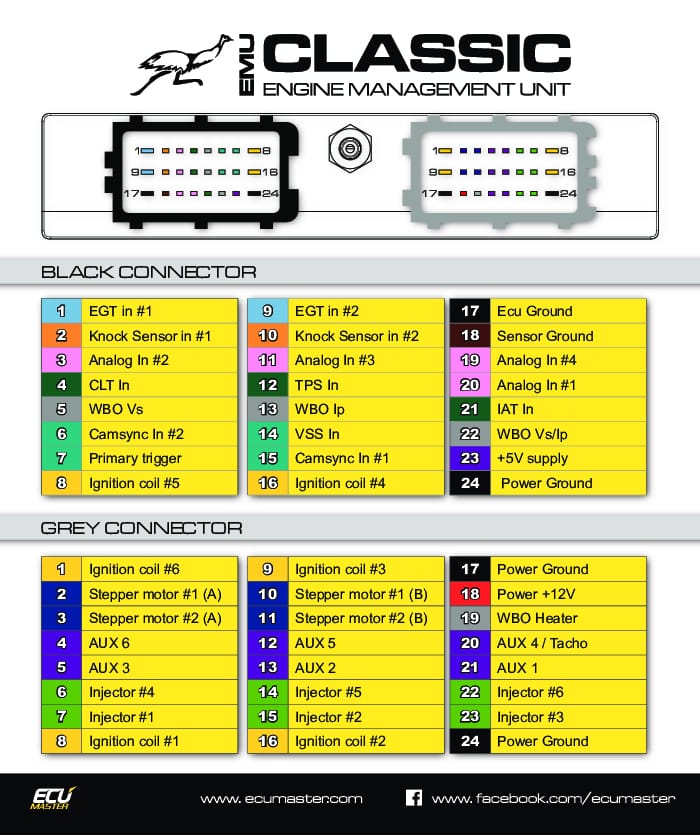
I dont have a pic of them, but i have connected the ign 4 to B16 output and ign 6 to G1, so the corresponding imput’s, but i will go to the car later and make a pic.
The reason for 4 and 6 is because i experimented on plugs G8 and G16, with the ign settings, so despite testing them o be OK, i want to use other ones just to be sure. if that makes sense.
I have not checked if i have 12v when cranking, but its connected to a factory 12v wire that was used to power some relay, so when the ignition is on it has 12v.
I dont know the answer to the trigger tooth. I understood that it means where no.1 tooth is, because its located 258 deg. BTDC (That was noted by others who have successfully converted the engine to a Megasquirt.)
Ok, i will change the option to the 7A 58mJ option.
I might be barking up the wrong tree, so take this with a grain of salt.
I’ve been studying your scope. It looks like the gap between tooth 58 and tooth 0 (zero) is not satisfying the condition to qualify the home signal.
For a 60 - 2 Trigger Wheel the computer is using the following calculation to find the Gap so it can begin the count from tooth zero every 360 degrees of Crank Rotation.
If the Gap Between Previous two teeth = ‘x’
Then the missing teeth are located where the (Gap between Previous tooth, and Current tooth)*0.4 is Greater than ‘x’
For example;
Gap between tooth 57 and 58 = 5.8
Gap between tooth 58 and tooth zero = 8.4
8.4 x 0.4 = 3.36
Since 3.36 is not Greater Than 5.8 the ECU has not calculated a space where 2 missing teeth are.
This is the common trend in your scope trace.
This could be caused by a loose sensor, incorrect air gap, damaged teeth, or incorrect trigger wheel selection e.g if it is a 60 - 1 for example.
EDIT:
I should say, just to be clear, that the computer is measuring these gaps in ‘time’ not distance.
This means a change in crank speed can cause anomalies in the pattern.
A very weak starter Battery could cause the crank to slow down enough on the compression stroke to disrupt the calculation of the missing teeth gap.
wrong edge selected on primary
Hi, was at the car right now, and tried rising edge detection it didnt trigger any spaek events on the light.
But i did some scopes with different number of teeth.
I will attach the files in a bit. They can be found in the trigger teeth number folder
Again no spark’s were registered on the timing light
But i took a pic of my harness, and yes its ugly but i am just testing it, and i dont have enough time to make a “better” one.
And yes the sensor grounds are joined together by an aligator clip.
So here it is visible G1 and B16 for ign outputs.
The value of quality wiring termination can not be over stated. You should definitely make all those ground connections properly.
You should not need to experiment with the physical trigger characteristics, i.e. the number of teeth on the reluctor wheel. The number of teeth is a physical attribute of the wheel that doesn’t change. You can only know if you have this right by examining the part itself. Changing software settings will only cause more problems. It is clear from the scope that there are 58 Teeth on what appears to be a 60-2. I only mentioned wrong trigger type settings as an example of something that can cause trigger problems. When you’re certain what type of trigger wheel your engine has you don’t need to worry about it.