I use a user function with Invert output option for reverse lockout. With the engine running I could not get the output to work correctly by activating Invert output. I could not get into reverse. I had to restart the EMU, activate Invert output and the start the engine to get it to work.
I have the same problem.
Version: 3.031
Description:
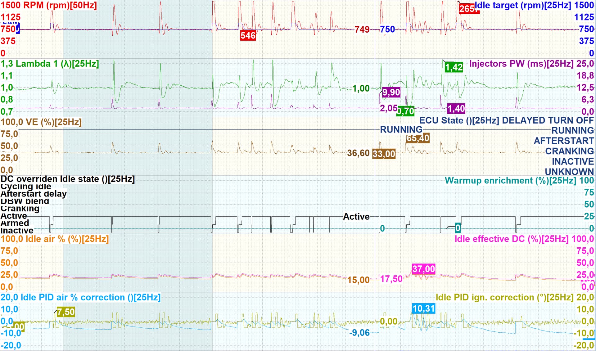
Idle air % channel seems not to show the table values it should display. In my application the channel shows much smaller values than present in the Active state air flow table. I am using a PWM style actuator with an I-type airflow and P-type ignition controller. The smallest value in my Active state air flow table is 23 %, but the Idle air % channel shows values much smaller (see log). Also the difference between Idle air % and Idle effective DC does not reflect the Idle PID air % correction. I am not using an idle custom correction.

You can work around the problem by negating your function and not using Invert output. For this you have to exchange AND by OR and OR by AND and negate your conditions.
In my case (the NOT being the activated Invert output):
NOT ((RPM < 1500 rpm) AND (Vehicle speed < 5 km/h))
equals
(RPM > 1500 rpm) OR (Vehicle speed > 5 km/h)
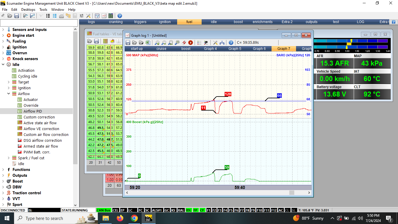
If I’m comparing MAP vs Boost values, the boost values are 6-8 KPA under MAP.
As an example on a 10PSI wastegate spring, MAP is 168 but boost may only read 27 KPA. If it was a 1:1 shouldn’t the boost value be 68 KPA or am I interrupting that wrong.
For PWM-controlled solenoids, an Airflow % value of 0 means that the Duty Cycle (DC) will be equal to the Solenoid minimum DC, and a value of 100% means that the DC will be equal to the Solenoid maximum DC.
Boost is MAP - Baro
What is your Baro on the log ?
I will have to look when I get home at the last log I recorded. I’m trying to use a stock 1JZ map sensor as a baro since I am using the internal MAP sensor.
The idle min. DC is 3 %. This is still very inconclusive.
@Jadzwin_ECUMASTER I have a question about the software.
In previous versions I could choose the color scheme of 3D graphs.
As someone who’s colorblind, the blue to red scheme was way more visible to me, this new scheme is harder to see. Is it possible to bring the old schemes back as an option?
and max ?
the idea is the airflow % is not a DC but a percent od the air provided by actuator.
There was no intention to disable different color schemes.
It seems it is a bug that this option disappear.
Will be restored in next version.
The idle max. DC is 100 %.
could youbplease post base map and log with problem with airflow %
your baro is for sure wrong.
thanks, I will swap out the sensor for a GM sensor I have known good calibration values for tomorrow and try it again.
Switching to the GM sensor fixed the issue.
Could you please show me the function that doesnt work with invert output ?
The changes in the functions are applied when OK button on the function editor is pressed.
The invert works directly on the output of the function, so it should be applied immediately after pressing OK.
Invert wasn’t written to the project file, but in application it should work immediately (I’ve check also on the bench and it works good).
Output of function Fn2 is AUX2.
Fn2: RPM < 1.500 rpm AND VSS < 5 km/h
After I did hit „Ok“ I could hear some clicking from the engine/gearbox every time.
I rewrote the function to work without Invert output. You do have my project file also.