Hello.
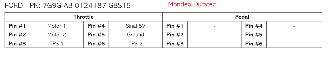
My throttle body is Ford 7G9G-AB.
The pedal is BV61-9F836-BB.
The throttle pinout looks like the screenshot I uploaded.
I think one of Motor1 and Motor2 is Motor+ and the other is Motor-, but does anyone know which is which?
I think one of TPS1 and TPS2 is POS and the other is POS INV, but which is which?
The pedal has 6 pins, but I couldn’t find the pinout even after looking. Also, the wiring diagram for the EMU Black only has four wires. Could you please tell me the correct way to connect it?
It doenst matter if motor + - is switched and also which is inverted tps…just connect it and if u see in SW that it is inverted then u can use the options to invert it…no more details about wiring needed.
for the Ford Focus pedals, i have come across 2 different wiring options.
1:
pins 1/6 - 5v
pins 3/4 - signal ground
pins 2/5 - signal outputs
2:
pins 1/4 - 5v
pins 2/5 - signal ground
pins 3/6 - signal outputs.
to verify you can measure resistance on the 5v and ground pins to confirm circuit. resistance value should be stable/fixed. outputs will have varying vaues as you move the pedal.
Did you ever figure out the pedal? I’ve been bench testing a throttle body and pedal from a 13 focus today. The throttle body works exactly as I would expect it to. Motor + and - with TPS signals that are opposite one another. However both sensors within pedal only output a signal voltage when they’re moved. It also seems this voltage is proportional to the speed at which the pedal is pressed. Is this normal behavior for this type of hall effect sensor?
It seems that what I was dealing with was a defective pedal. It’s supposed to put out a 0-5v signal proportional to how far the pedal is been pressed. Realistically you should be able to use just about any throttle by wire pedal that works in a similar way.