Hello everyone, now that the winter break is over, I can finally get back to working on the emu. Currently, I’m not satisfied with the motor start behavior and the prime trigger synchronization (current no emu synch possible). This affects both the VR signal and the Hall sensor signal as primary trigger. The signal curves look good on an external oscilloscope. However, the engine speed when starting is approximately 145 rpm. I’m afraid that’s not enough for the emu, although the Sensor signal strength (VR: ca. 700mV) itself is fine. Hence the question to the emu specialists: Whether the EMU Black requires a minimum cranking speed for the starting process ?
Regards, Frank
Is this still that 1.8T engine you had a previous thread on?
174 rpm is plenty for EMU synch, I think you had a different issue.
If the primary trigger signal with a VR sensor is 0.7V then that should be enough for synch.
Is both the crank and cam sensors using shielded wire?
Can you post a more recent trigger scope and file with your trigger settings?
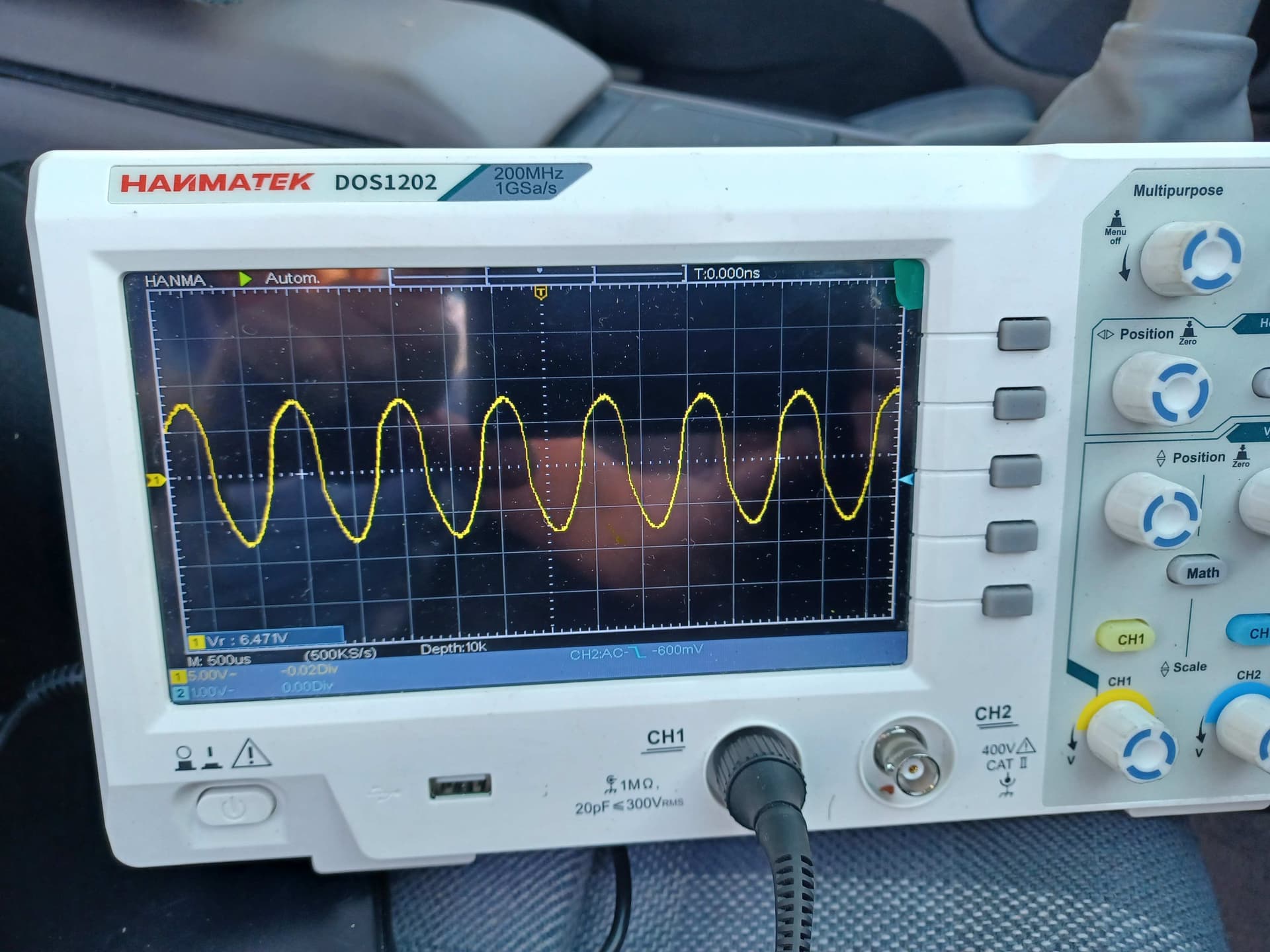
Hello, yes, I also wrote in the 1.8 post. However, in my case, I’m talking about a Porsche 4-cylinder engine with the 60-2 trigger concept. Derived from the 1.8t series concept. However, the 60-2 trigger wheel is handmade, and the VR sensor is the original series sensor. So, it’s all a far cry from the original Motronic. The engine ran very well for an event with the EMU Black. However, the starting behavior is unacceptable. Therefore, I’m looking for the problem. I’ve attached two recent pictures. The VR signal is converted and sent to the EMU as a Hall signal. I was actually hoping there was a starting rpm dependency. I’ll probably switch back to a new VR sensor to at least get back to last year’s status. Currently, there’s no sync with the emu.


can you post the project file, data log of that screen shot and a scope log?
Thanks for the reply. Just to be safe. Currently, I’m getting a starter speed of about 150 RPM when the engine is cold and the engine is not running. When i starting with a warm engine, the cranking speed was around 180 RPM and the engine is running fine. See also the two pictures. Are you sure that 174 RPM is the minimum required to start ??? Then that would be the perfect explanation for the problem.
I’ve since replaced the VR sensor again and i`am continuing to optimize the distance to the trigger.


never said 174 rpm is the minimum, in fact it’s plenty high enough. I’ve had engine that sync below 100 rpm and still start.
You need to post a tune file, scope log and data log. screen shots are a teaser
Do you have a picture of the trigger wheel you made? Hall and VR want different shapes
What’s the PN of the VR sensor and whats the air gap you’ve tried?
Okay, thanks for the correction. I’m assuming that my current trigger wheel and VR sensor combination is unfortunately far from optimal, and therefore the cranking speed could play a role.
I use the VR sensor Bosch 0 261 210 003. The actual air gap is 0.1 mm. This is barely enough for a cold start, and when the engine is running, it misfires at just over 6000 rpm.
With an air gap of 0.25 mm, it misfires at 5400 rpm, etc. I can still go to 0.05 air gap, but that’s not nice. I’ve attached the current logs (cold and warm) and an older, not-so-nice scope file.
I’ve also attached the project file and pictures of the trigger wheel. (Two teeth from the wheel were removed before assembly.) And, of course, there’s a 10k resistor in the VR signal line.
I’ve ruled out ground/connection errors. I’ve already tested with different VR lines and ground connection concepts.
Cold_Engine.emublog3 (32.5 KB)
Warm_Engine.emublog3 (1.7 MB)
Older_Scope_11_2024.emubscp3 (617 Bytes)


Project_File_VR.emub3 (60.9 KB)
ok so had a look at the map, cold and warm start as well as the scope.
is the erratic tps trace acutally your foot? like it’s physically possible that you can move that fast but I’ve also seen failing sensor traces that looked quire similar
What air gap was that oscilloscope photo taken at? the wave form kinda looks like the sensor polarity is inverted (as in the wires need to be swapped from + and -).
upon review with the scope log, cylinder 2 is firing ignition right on the gap tooth section, which really isn’t ideal. It actually appears to have double fired.
The trigger wheel is kinda small for a 60-2, I personally would have done a 36-1 or 36-2. But there are smaller 60-2 wheels out there that do work.
Why did you put a 10k resistor in series? I never add resistors into VR circuits, the ECU has a couple settings to mitigate noise and in a rare worst case scenario I’d add one. I can’t find a data sheet anywhere for that sensor, maybe you have specific info that I don’t?
The lack of accel enrichment is a bit concerning, but I’m assuming all this is still before you’ve driven the car at all and these trigger errors are occurring at free rev?
And I’ve asked this already but I know Porsche does shield their position sensors, and it sounds like you’ve tried running new wire which i’m also going to assume is, but the sensor is using shielded wire with only 1 side of the shield grounded?
I also notice on the warm log that your trigger errors are the same rpm as the ign rev limiter, but might be a coincidence. the way you have it set is when cold that rev limit is even lower.
Other possibilities for the hard starting is the lack of idle air control, incorrect injector data. The main fuel table seems extremely low VE numbers to me which is a red flag.
The project file is only a working interim version. There are still some adjustments to be made.
The oscilloscope photo is a bit older. Not of the current VR sensor. The air gap was maybe around 0.4mm.
The scope file is also a bit older. I’ll create a new scope file just to be on the safe side.
Yes, the trigger kit actually originally included a 36-1 wheel. But the 60-2 should actually work better, or rather, it’s the standard for many vehicles. That wasn’t my idea, though.
The diameter is slightly larger than the minimum specified size for a 60-2 trigger wheel.
I think in my case it’s an unfortunate combination of trigger wheel and VR sensor.
In the series, the sensors are only shielded on the DME/ECU side. Exactly as Ecumaster specifies. I rule out reverse polarity.
Let’s see what the curve currently looks like on the oscilloscope. I can swap the plus and minus signals for testing.
The 10K resistor comes from the EMU info/help function. See the hard copy. The motor only runs with the resistor.
With all filter settings (I tested all combinations), various trigger error messages constantly appeared.
I’ll keep an eye on the VE values.
Update to follow.

Unfortunately, I don’t have a datasheet for the VR sensor. The cable length on the sensor is 380mm, and the resistance is 0.86 kOhm.
Hello Tyson,
The VR sensor on the car is now working. There are no more misfires at high revs.
I further reduced the sensor gap (approx. 0.05 mm) and increased the resistance in the VR signal line slightly. I know this doesn’t meet the EMU specifications. But the car is running so quite right. I also installed a new starter (with a higher rpm). The engine starting behavior definitely benefits from this. I might switch to the following Bosch sensor in the future: 0 986 280 475. The sensor is significantly more modern than the stock sensor. I’ve attached the “imperfect” scope file for it.
Thanks for the tip about the TPS signal. I’m not satisfied with it either. The overrun fuel cut-off also reacts very quickly. However, I only found two “filter” positions in the TPS settings. You probably mean that the TPS curve needs to be customized? I’m also attaching the project file and two current images from the oscilloscope. I think they’re fine. The shadows come from inaccurate triggering or from the camera. Thank you very much for your efforts and Happy Easter.
scope_2025412_1644.emubscp3 (617 Bytes)
20250415_New_Lamda.emub3 (63.7 KB)

Happy easter to you as well,
Scope logs look good, much cleaner wave shape then previous.
Glad to hear that solved your misfiring at rpm.
The TPS trace I was referring to was wondering out loud if the pedal was actually moving that fast. You can do a sweep test to see if there’s any worn spots on the sensor, just press the pedal slowly and watch the voltage steadily increase. Sometimes it does take the engine running to find a dead spot.
I was also looking at the lack of acceleration enrichment as all the tables for that are set to 0 and it’s not adding fuel on tip in.
The TPS curve is not adjustable with a cable throttle beyond calibrating voltage at open and closed.