It looks like something backfeeding the ECU.
The wiring diagram is only written in Japanese, but FC1 in this diagram is the fuel pump relay signal.
It’s really strange that the behavior is different between the first 3 seconds after turning on IG (currently set to 3 seconds) and after that.
I’ll also consider the possibility of backfeeding.
In addition to that I’ll try changing the fuel pump control from HighBridge1B to Aux2.

Aren’t there two maps to choose from in the ALS strategy, or did I miss it somewhere?
where do I set the fuel cut? Previously it was in v2 fuel cut under xx psi. For me with v3 fuel does not switch off when coasting above 3000rpm
I just changed the fuel pump control from HighBridge1B to Aux2.
It is working properly now.
The state immediately after power is turned on and when HighBridge is inverted and controlled by GND (in this case when the Fuel Pump is driven and then stopped)
Aren’t these two states different?
I’m going to continue using Aux2 for the fuel pump.
Perhaps the same thing would happen if I controlled another circuit?
Or is there something I need to do on the connected circuit side?
It is overrun startegy right now
The explanation was not translated well, so I’ll add a supplement.
I think the state is different when the IG is turned off while the fuel pump is running and when the IG is turned off while the fuel pump has stopped running (it started once and then stopped).
sorry for the wait but i did some test…the minimum oil temperature is right and the vvt work well…i share the map and recent log,when downshift a gear the vvt works,is right?..a dq250 method similar to v2 over 630nm is possible?with v2 i didn’t have the torque limit
13 3 25.emub3 (64.5 KB)
13 2 25 log.emublog3 (3.1 MB)
scope_2025213_1616.emubscp3 (649 Bytes)
VVTi works all the time.
DQ250 CAN stream is limited to 620Nm and it is not possible to send more from ECU (it is manufacturer limitation).
Hi, I have the same problem, emu is connected to oem wiring harness as per instructions in ecumaster USA materials - v2 works as expected and emu powers off when I turn off the key, v3 stays on and drains the battery. It looks like it could be the fuel pump and mac valve connected to aux outputs. What exactly changes from v2 to v3 that the backfeed starts to be a problem? Can I somehow fix it without changing the wiring?
I think you have something active when engine is not running (but ign is on), what is not active in V2, what cuase backfeed.
You can try disconnect fuel pump or mac valve and check if it helps.
It will help to find the reason.
I’ve found the culprit. It’s IACV - when disconnected emu powers off as expected. Still, I do not understand why v2 powers off with it connected and v3 does not. I’ve checked the settings and i can’t see anything that looks suspisious.
@Jadzwin_ECUMASTER ? Has something changed regarding aux outputs handling between v2 and v3? Is it possible to add some option to set them to work similar to v2 so there is no need to modify oem harness?
use functions for them and they will work exactly the same way and actually is more functional on v3
The feedback is probably via the flyback diode of AUX3.
Normally the Black has two power lines: battery and ignition switch, that must be separate. The all flyback circuits are connected to the battery so they cannot backfeed the ignition circuit.
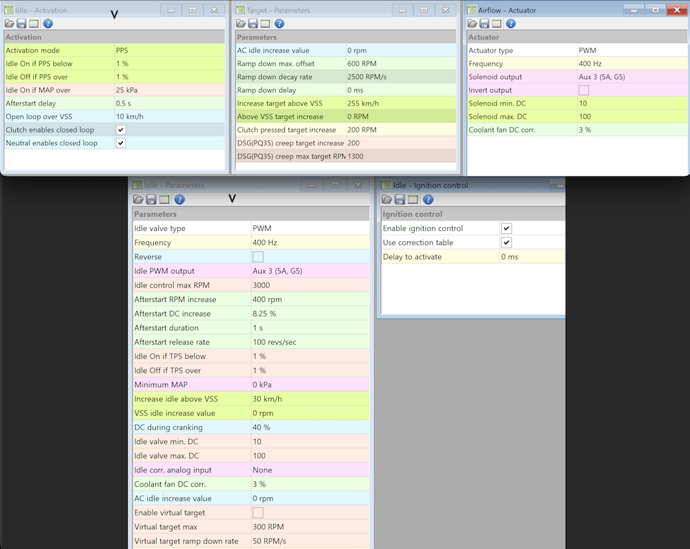
What you can check is to set idle PWM output to None and then use function set the Aux 3 output active. Then check if the ECU switches off.
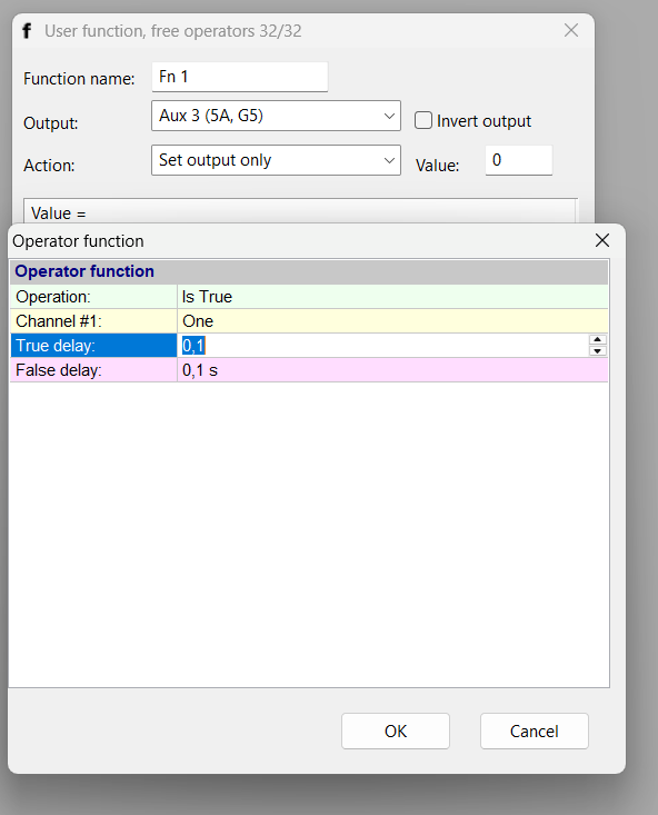
I’ve played around with the functions, and it works — when the function is active on AUX 3, the ECU powers off. It feels a little “hacky,” but I came up with a function that activates on key-off: the ECU state has to be inactive, and CAN must be disconnected (I have an ADU, and it powers off with key-off). This way, the IACV doesn’t make weird noises when the engine is off.
Another thing I’m curious about is why the P and I parameters in alternator control are capped at a maximum value of 31.25? I’ve tuned the alternator PID, and it looks like the max values work best for my application — maybe even higher values would work better?
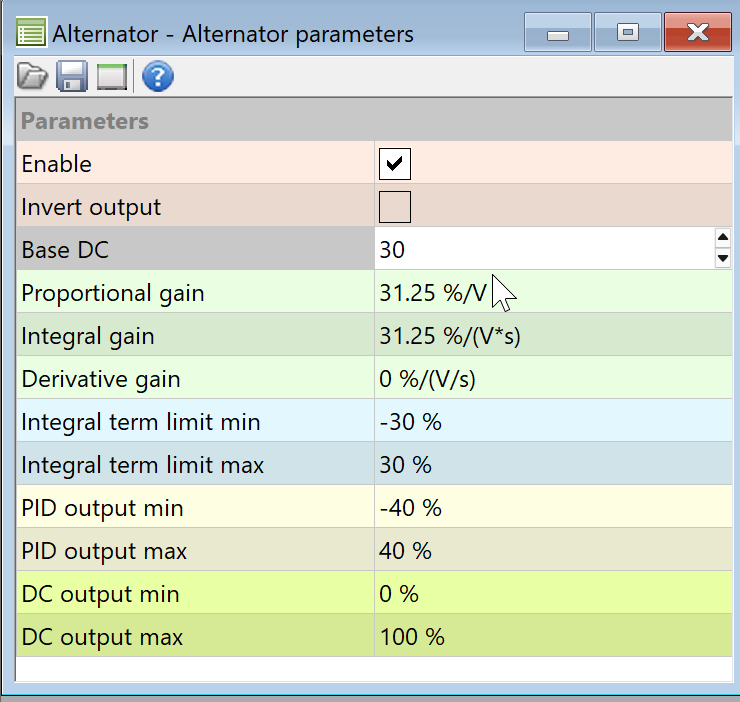
It is a limit of signed 16 bit integer number.
However your PID control and integral parts are limited. You can try to change PID putout min / max.
Could you please send a log file with battery voltage regulation ? Please select in options Other/PID monitors/ Pid controller - Altertnator option
I have this log with settings from previous post and alternator pid monitor. I’ve changed voltage target couple of times to show how it works. Integral is getting big on idle but larger base DC causes problems in higher rpms.
alternator.emublog3 (180.9 KB)
On idle it looks good. Do you have log from high RPM ?
I can make the BASE DC as a 2D table as a function of RPM.
sorry, I forgot to post the log. It only goes up to 4500 once, but maybe it will be enough.
alt pid.emublog3 (2.0 MB)