So, I had dbw working in V2. All i did in that softwware version was tell it I was working with Toyota 46010, having all wiring correct, and the DBW Calibrating Tool worked fine. I have been moving on to V3 just because I enjoy even more functionality but CANNOT get DBW to work. I’m using the GS300-IS300 base map as a start point and I think I have enough there to get the car to start, except the dbw does not work. Its a vvti 2jzgte.
The last thing i did was take pin B18 (TPS In) and relocate it to B30 (Analog 4). Then went to sensor and under TPS i directed it to look at B30 instead of at “TPS”. Still the DBW tool is telling me to fix the settings. Not quite sure what I am missing so if someone can take a look and let me know where i am being stupid I’d appreciate it.
It continuously asks me to fix my PPS settings. Ive tried several setups with no luck. Ive also looked at log and can see when voltage is registered and when nothing comes up.
I have VTA/VTA2 and VPA/VPA2 wires. Ive tried several configs but no luck. Will continue to try, your time is appreciated!
These are my settings. Got home too dark to do wiring but from listening to the TB the butterfly is opening when i depress the pedal and voltage is showing across both sensors. With these settings the error when i run the DBW Autotune is that the motor is not moving, even though if i press the pedal you can clearly hear it opening.
I relocated pins to TPS and to B31 respectively and now the calibration tool does its thing. Im getting the car to idle for a while but it shuts itself off upon reaching something like 200F CLT. I’ll continue to troubleshoot, its definitely wiring related
Make sure you have your wiring pinned to the correct locations. Double and triple check. If it is, then you need to make sure that in your TPS/PPS settings you are telling the unit WHERE the wires are pinned to, i.e. TPS to TPS (Black 18) and PPS to Analog 1 (Black 31)
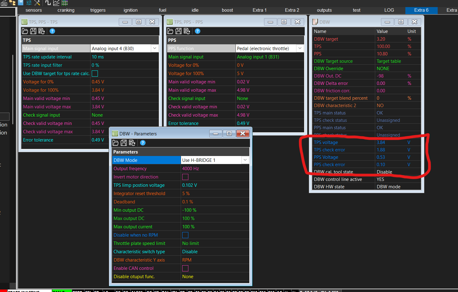
At this point I have checked and double checked my DBW wiring and am pretty confident it is correct. It is, after all, not that complicated. When running the calibration tool I am getting the following numbers, followed by the error message. 3.82V closed throttle voltage sounds troll so I am chalking it up to a bad sensor and ordered a new one. Hopefully installation of TPS isnt as disastrous as I remember some installations being where you could never get it quite right. Comments on other settings are welcome but this screenshot was taken at a point where I wwas just shooting at a wall and seeing what stuck.
No luck. It doesnt like anything put into the check signals box. I am going by the below diagram and trying to understand what the unused VTA2 VPA2 are. I assumed they could be the signal check but if i assume this and wire it accordingly it doesnt work. I’ve put VTA into TPS and VPA into Analog 1 and vice versa to no avail. I may just shove the car off a cliff
Yeah the signal 2 wires are an opposite of the signal 1 wires, its used to know exactly where the pedal/throttle is, (open a log page and you should see the voltages and if they match your settings for min/max voltages, they should each have a 0-5v and a 5-0v reading) Although with check signal disabled I’d expect it should work with just 1 sensor on pedal and 1 on throttle.
I have my new sensor but theres obviously something crossed up somewhere. I will inevitably have to undo the harness…im actually considering just splicing wires and running them directly to the emu instead of undoing the harness. Situation being a closed throttle voltage of 3.82V is clearly wrong and it is what the new TPS is reading as well. I’m going insane wondering how i had gotten it to work and what could i have possibly changed to mess it up.